
NEWSLETTER #96 SEPTEMBER 2021
Shipmate,
Instead of the usual newsletter, I want to share portions of PSMA’s Maintenance Manager Jim Wakefield’s reports to the Board of Directors concerning the installation of a Type 8b periscope. The scope is coming from a former Elk’s Club in North Hampton, MA after the club shut down.
The periscope is 36 feet long and weighs approximately 2,000 lbs. It comes with a support pedestal that supports the periscope with the eye piece located approximately 5 feet above the floor. The pedestal has an attached step for children’s access to the eye piece. The stainless steel section at the top of the pedestal attaches to the bottom of the scope and contains a ball (or roller) bearing which allows the periscope to freely rotate 360°. The periscope requires an upper support bearing which is not accompanying the donated scope and PSMA will have to have one manufactured. The support bearing is not complex, drawings are available, and the cost to manufacture is not anticipated to be high.
Mr. Paul J. Lapinski, an ex-employee of Kollmorgen, the manufacturer of the scope, is the primary individual responsible for the donation of the scope to PSMA. Mr. Donald Anderson will be transporting the scope to Albacore Park and is donating $1000.00 of the transportation cost. Mr. Robert P.
Cahillane is donating the remaining $500.00 of the transportation cost. Another gentleman, also an ex-employee of Kollmorgen and a periscope technician, will assist us in the installation, reassembly of the scopes components and assure the scope is fully functional.
I am proposing a location for installation just inside the door from the Lobby/Gift Shop slightly North of the current USS Dolphin Display Case. We are fortunate that the location is directly over a large concrete footing, and a carrying timber with a support post. No structural modifications will be required to support the weight of the scope. The location is approximately 8’-6” from the East wall and 7’-6” from the south wall.
Unfortunately the ideal location interferes with the roof ridge and an HVAC vent in the ceiling. The scope will need to be located approximately 12 inches from both the ridge and vent. Another issue is that there is no access the that East end of the attic, a hatch will need to be cut into the vaulted ceiling in the scope’s general vicinity to allow access for installing the scope support bearing and roof penetration. Installation of the scope in the proposed location will result in the scope protruding from the roof by approximately 20 feet.
When the ideal location for the periscope was identified, it happened to be precisely where one of the HVAC vents in the ceiling was located. In order to accomplish all of the work in the attic, walking flats had to be installed the entire length of the attic as well as temporary power and lighting. When that was completed, the next step was to relocate the vent. lighting. When that was completed, the next step was to relocate the vent. That was accomplished several weeks ago and a photo follows. Please notice the 16” medallion trim I purchased for the scope did not cover the entire area where the vent was located. I have enlarged the medallion with a flange so that on final installation the entire discolored area will be covered. The next step of the installation involved reinforcing the floor of the museum to support the load of the periscope and support pedestal. The periscope weighs 1537 lbs. and the pedestal (my estimate after horsing the thing around several times) is no more than 300 lbs. The scope location happened to be directly above a 3 ft. wide concrete footing, a carrying timber, and a 4” X6” support post. Based on my current knowledge of the combined weight of the scope and pedestal, (did not have that data until recently) existing support would have been adequate. However, Ken Latchaw and I determined that some additional support would add a safety factor, would be easy to install, and would be relatively inexpensive. The resulting structure, installed by Ken Latchaw and George Millikin, is shown below and it will support a ridiculous load of approximately 60 Tons (Cheryl, don’t check my math and embarrass me).


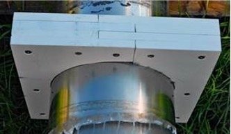
The next phase required the installation of a ceiling penetration tube, manufacture and installation of a foundation in the attic, on the ceiling joists, to support an upper support bearing for holding the scope vertical and allowing full rotation. We also had to have the upper support bearing manufactured. This has all been accomplished as depicted in the following photo. This actually came out better than expected with the bearing perfectly level, digitally measured with 0.1° accuracy, both north-south and east-west. In addition to installing the bearing, one of the roof rafters required a section to be cut out and an area for the scope to penetrate the roof framed. Please notice the framed area between the rafters as I will address this area again later in this report.
The pedestal required work as well to improve its appearance and maintain its working parts. The pedestal has been repainted, the child step re-carpeted, the thrust bearing cleaned and re-packed, the periscope support plate/bearing cap cleaned and repainted, and the stainless steel skirt cleaned and polished. Please note that the center area of the bearing cap has been cleaned but not painted. The bottom of the scope has also been cleaned so the two mating surfaces will have direct contact and electrical conductivity. Photos follow. Our Executive Director had pointed out that the installed scope would be an awesome lightning rod. In order to resolve this potential serious problem, with Dick Wilder's assistance, a solution was devised. Conductivity will be maintained through the scope, the pedestal, the pedestal base securing fasteners, a heavy duty ground wire to a ground in the basement. Please also note that the pedestal is precisely located directly below the center of the upper support bearing. The pedestal will not be secured to the floor until the periscope is set, secured, and verified to rotate freely without binding.


Although the relative short distance between the bottom of the scope on the pedestal and the upper support bearing (9’ 6”) is considered adequate and safe for virtical support, I wanted to add some additional support as there would be approximately 22’ of scope above the roof. Luckily I had sufficient acrylic ploymer sheet left over from one of my recent personal projects to fabricate an interlocking, split support bushing that I will install at the roof level, within the rafter framed area approximately 4’ above the upper support bearing after the scope is installed. This bushing is complete and trial fit.
There needs to be a counter flashing for the scope’s roof penetration for weather protection. Below you will see the roof flashing module and the counter flashing mounted on the scope. The flashing will be installed when the scope is installed. I have contracted Veterans Builders, LLC to support the installation, strip the shingles, cut the hole in the roof, and position the flashing while the scope is lowered through it into position. The flashing will be centered around the scope when the scope is secured and the height of the counter flashing is adjusted to the proper height.


As of today we are ready to install. Ken Latchaw has arranged for Moore Crane Service to rig the scope into the museum. Paul Lipinski is not available to assist with the rigging (he has the custom periscope rigging gear) and final assembly until 28 September. Both Veterans Builders and Moore Crane Service have been comfirmed for that date. Mr. Lapinski cannot arrive at Albacore Park until 10 – 11 am. I will have everything ready with the hole in the roof by 10 am and the scope should be landed by 12 or 1 pm. Final assembly of the scope, restoration of the roof, securing the pedestal to the floor, installing the ground, and installing the counter flashing will take the rest of the day. I will install the additional support bushing at the roof level within the following few days.


To date, the final expected cost to PSMA will be approximately $3,400.00, slightly above my initial estimate and $400.00 above the board’s authorized amount. This figure includes the cost for the carpenter and crane service, which are estimates.
Respectfully,
Jim
As noted above, even free things are not truly free. The Albacore Shipmates will donate $500 toward the cost of the scope’s installation.
Austin ‘Butch’ Jordan has a new email address of “beej1123@aol.com”. Mike Nowicki and Carole have relocated to 99 Taylor Drive, Decherd, TN 37324. His email of “wdnciths9@gmail.com” is unchanged. John Gandiello has a new email of gandiello@outlook.com.
Until next time, shipmate, stay safe and stay healthy.
Jack Hunter 11 Admiralty Drive, Apt 3 11 Admiralty Drive, Apt 3
Middletown, RI 02842-6254
(401) 849-7282
“jhunter2007@cox.net”